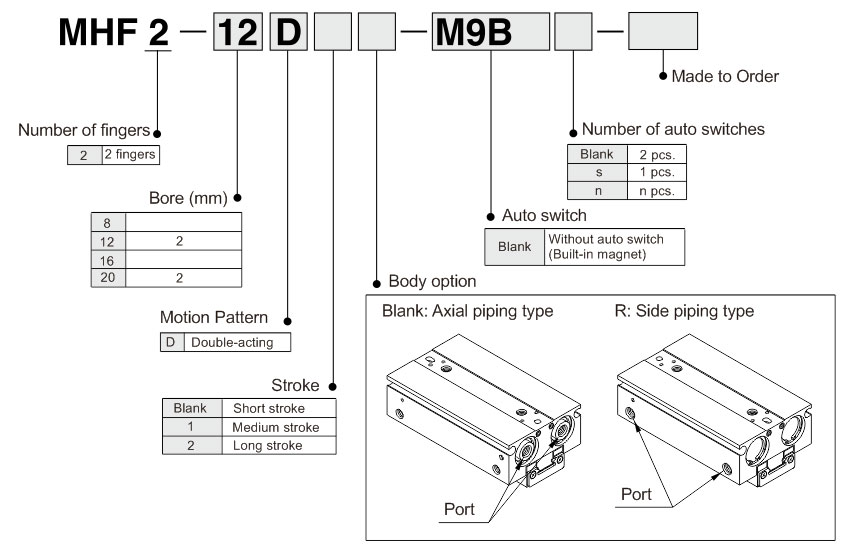
Model and Meaning
Applicable Auto Switches
| Type |
Special functions |
Electrical entry |
Indicator light |
Wiring
(Output) |
Load voltage |
Auto switch model |
Lead wire length (m)* |
Pre-wired
connector |
Applicable load |
| DC |
AC |
Perpendicular |
In-line |
0.5
(Nil) |
1
(M) |
3
(L) |
5
(Z) |
| Solid state auto switch |
-- |
Grommet |
Yes |
3-wire (NPN) |
24V |
5V,12V |
-- |
M9NV |
M9N |
● |
● |
● |
○ |
○ |
IC circuit |
Relay, PLC |
| 3-wire (PNP) |
M9PV |
M9P |
● |
● |
● |
○ |
○ |
| 2-wire |
12V |
M9BV |
M9B |
● |
● |
● |
○ |
○ |
- |
Diagnostic
indication
(2-color indicator) |
3-wire (NPN) |
5V,12V |
M9NWV |
M9NW |
● |
● |
● |
○ |
○ |
IC circuit |
| 3-wire (PNP) |
M9PWV |
M9PW |
● |
● |
● |
○ |
○ |
| 2-wire |
12V |
M9BWV |
M9BW |
● |
● |
● |
○ |
○ |
- |
Water resistant
(2-color indicator) |
3-wire (NPN) |
5V,12V |
**M9NAV |
**M9NA |
○ |
○ |
● |
○ |
○ |
IC circuit |
| 3-wire (PNP) |
**M9PAV |
**M9PA |
○ |
○ |
● |
○ |
○ |
| 2-wire |
12V |
**M9BAV |
**M9BA |
○ |
○ |
● |
○ |
○ |
- |
** Water resistant type auto switches can be mounted on the above models, but in such case SMC cannot guarantee water resistance.
* Lead wire length symbols: 0.5m……………Nil (Example) M9NW
1m…………… M (Example) M9NWM
3m…………… L (Example) M9NWL
5m…………… Z (Example) M9NWZ
* Auto switches marked with "○" are made to order specification.
Note) When using the 2-color indicator type, please make the setting so that the indicator is lit in red to ensure the detection at the proper position of the air gripper.
Specifications
| Fluid |
Air |
| Operating pressure |
ø8 : 0.15~0.7MPa |
| ø12~20 : 0.1~0.7MPa |
| Ambient and fluid temperature |
-10~60℃ (with no condensation) |
| Repeatability |
Note 1) ±0.05mm |
| Maximum operating frequency |
Short stroke |
120c.p.m. |
| Medium stroke |
120c.p.m. |
| Long stroke |
60c.p.m. |
| Lubrication |
Not required |
| Action |
Double acting |
| Auto switch (Option) |
Solid state auto switch (3-wire, 2-wire) |
Note 1) This is the value when no offset load is applied to the finger.
When an offset load is applied to the finger, the maximum value is ±0.15 mm due to the influence of backlash of the rack and pinion.
Model
| Action |
Model |
Bore (mm) |
Gripping force (Note 1) |
Opening/closing stroke (both sides) mm |
Weight (g) (Note 2) |
Unobstructed capacity (cm³) |
| Effective gripping force per finger N |
Finger open side |
Finger close side |
| Double acting |
MHF2-8D |
8 |
19 |
8 |
65 |
0.7 |
0.6 |
| MHF2-8D1 |
16 |
85 |
1.1 |
1.0 |
| MHF2-8D2 |
32 |
120 |
2.0 |
0.9 |
| MHF2-12D |
12 |
48 |
12 |
155 |
1.9 |
1.6 |
| MHF2-12D1 |
24 |
190 |
3.3 |
3.0 |
| MHF2-12D2 |
48 |
275 |
6.1 |
5.8 |
| MHF2-16D |
16 |
90 |
16 |
350 |
4.9 |
4.1 |
| MHF2-16D1 |
32 |
445 |
8.2 |
7.4 |
| MHF2-16D2 |
64 |
650 |
14.9 |
14.0 |
| MHF2-20D |
20 |
141 |
20 |
645 |
8.7 |
7.3 |
| MHF2-20D1 |
40 |
850 |
15.1 |
13.7 |
| MHF2-20D2 |
80 |
1225 |
28.0 |
26.6 |
Note 1) At the pressure of 0.5 MPa, when gripping point L is 20 mm.
Note 2) Excluding the auto switch weight.
Symbol

Made to Orde
| Symbol |
Specifications/Description |
| -X4 |
Heat resistance (100℃) |
| -X5 |
Fluororubber seal |
| -X50 |
Without magnet |
| -X53 |
EPDM seal/Fluorine grease |
| -X63 |
Fluorine grease |
| -X79 |
Grease for food processing machines, Fluorine grease |
| -X79A |
Grease for food processing machines |
| -X81A |
Anti-corrosive treatment of finger |
| -X81B |
Anti-corrosive treatment of finger, guide and joint |
| -X83 |
With an adjustable opening/closing finger positioning |
Structure Drawing
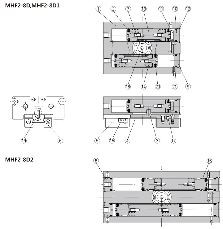
Component Parts
| No. |
Description |
Material |
Note |
No. |
Description |
Material |
Note |
| 1 |
Body |
Aluminum alloy |
Hard anodized |
11 |
Head damper |
Urethane rubber |
|
| 2 |
Piston |
Stainless steel |
|
12 |
Clip |
Stainless steel wire |
|
| 3 |
Joint |
Stainless steel |
Heat treatment |
13 |
Rack |
Stainless steel |
Nitriding |
| 4 |
Guide rail |
Stainless steel |
Heat treatment |
14 |
Magnet |
- |
Nickel plated |
| 5 |
Finger |
Stainless steel |
Heat treatment |
15 |
Steel balls |
High carbon chromium bearing steel |
|
| 6 |
Roller stopper |
Stainless steel |
|
16 |
Wear ring |
Synthetic resin |
|
| 7 |
Pinion |
Carbon steel |
Nitriding |
17 |
Roller |
High carbon chromium bearing steel |
|
| 8 |
Cap A |
Aluminum alloy |
Clear anodized |
18 |
Needle roller |
High carbon chromium bearing steel |
|
| 9 |
Cap B |
Aluminum alloy |
Clear anodized |
19 |
Parallel pin |
Stainless steel |
|
| 10 |
Cap C |
Aluminum alloy |
Clear anodized |
20 |
Piston seal |
NBR |
|
|
|
|
|
21 |
Gasket |
NBR |
|
Replacement Parts
| Description |
Kit Model |
Contents |
| MHF2-8D |
MHF2-8D1 |
MHF2-8D2 |
| Seal kit |
MHF8-PS |
MHF8-PS-1 |
MHF8-PS-2 |
12, 20, 21 |
| Finger assembly |
MHF-A0802 |
MHF-A0802-1 |
MHF-A0802-2 |
3,4,5,6,15,17,19 Mounting screw |
Replacement part/Grease pack part model:
Guide unit: GR-S-010 (10g)
Cylinder unit: GR-L-005 (5g)
Bolts for Body Through-hole Mounting
| Part Model |
Number of pieces |
| MHF-B08 |
MHF2-8D |
2 pieces/unit |
| MHF2-8D1 |
2 pieces/unit |
| MHF2-8D2 |
4 pieces/unit |
* The bolts for body through-hole mounting are attached to the product. They are also provided at an order of 1 piece or more with the above part numbers.
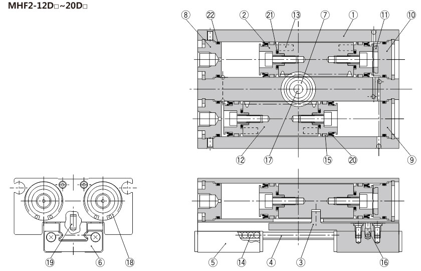
Component Parts
| No. |
Description |
Material |
Note |
No. |
Description |
Material |
Note |
| 1 |
Body |
Aluminum alloy |
Hard anodized |
13 |
Magnet |
− |
Nickel plated |
| 2 |
Piston |
Stainless steel |
|
14 |
Steel balls |
High carbon chromium bearing steel |
|
| 3 |
Joint |
Stainless steel |
Heat treatment |
15 |
Wear ring |
Synthetic resin |
|
| 4 |
Guide rail |
Stainless steel |
Heat treatment |
16 |
ø12 : Roller |
High carbon chromium bearing steel |
|
| 5 |
Finger |
Stainless steel |
Heat treatment |
ø16~20 : Parallel pin |
Stainless steel |
|
| 6 |
Roller stopper |
Stainless steel |
|
17 |
Needle roller |
High carbon chromium bearing steel |
|
| 7 |
Pinion |
Carbon steel |
Nitriding |
18 |
ø12 : R shape retaining ring |
Carbon steel |
Phosphate coated |
| 8 |
Cap A |
Aluminum alloy |
Clear anodized |
ø16~20 : Type C retaining ring |
| 9 |
Cap B |
Aluminum alloy |
Clear anodized |
19 |
Parallel pin |
Stainless steel |
|
| 10 |
Cap C |
Aluminum alloy |
Clear anodized |
20 |
Piston seal |
NBR |
|
| 11 |
Head damper |
Urethane rubber |
|
21 |
Gasket |
NBR |
|
| 12 |
Rack |
Stainless steel |
Nitriding |
22 |
Gasket |
NBR |
|
Replacement Parts
| Description |
Kit Model |
Contents |
| MHF2-12D |
MHF2-12D1 |
MHF2-12D2 |
MHF2-16D |
MHF2-16D1 |
MHF2-16D2 |
MHF2-20D |
MHF2-20D1 |
MHF2-20D2 |
| Seal kit |
MHF12-PS |
MHF12-PS-1 |
MHF12-PS-2 |
MHF16-PS |
MHF16-PS-1 |
MHF16-PS-2 |
MHF20-PS |
MHF20-PS-1 |
MHF20-PS-2 |
12, 20, 21 |
| Finger assembly |
MHF-A1202 |
MHF-A1202-1 |
MHF-A1202-2 |
MHF-A1602 |
MHF-A1602-1 |
MHF-A1602-2 |
MHF-A2002 |
MHF-A2002-1 |
MHF-A2002-2 |
3,4,5,6,15,17,19 Mounting screw |
Bolts for Body Through-hole Mounting
| Part Model |
Number of pieces |
| MHF-B12 |
MHF2-12D |
2 pieces/unit |
| MHF2-12D1 |
2 pieces/unit |
| MHF2-12D2 |
4 pieces/unit |
* The bolts for body through-hole mounting are attached to the product. They are also provided at an order of 1 piece or more with the above part numbers.
* When mounting MHF2-16D or MHF2-20Dwith the body through-holes, use hexagon socket head screws available on the market.
Replacement part/Grease pack part model:
MHF2-□□D, D1(ø12,16,20)
MHF2-□□D2(ø12) |
GR-S-010(10g) (Guide unit) |
| GR-L-005(5g) (Cylinder unit) |
| MHF2-□□D2(ø16,20) |
GR-S-010(10g) (Guide unit) |
| GR-L-010(10g) (Cylinder unit) |
Dimensions
MHF2-8D
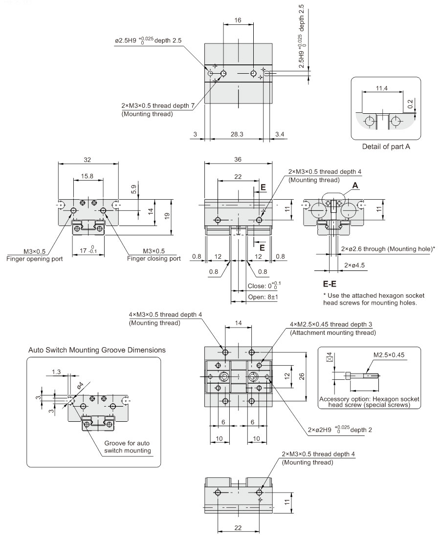
MHF2-8D1
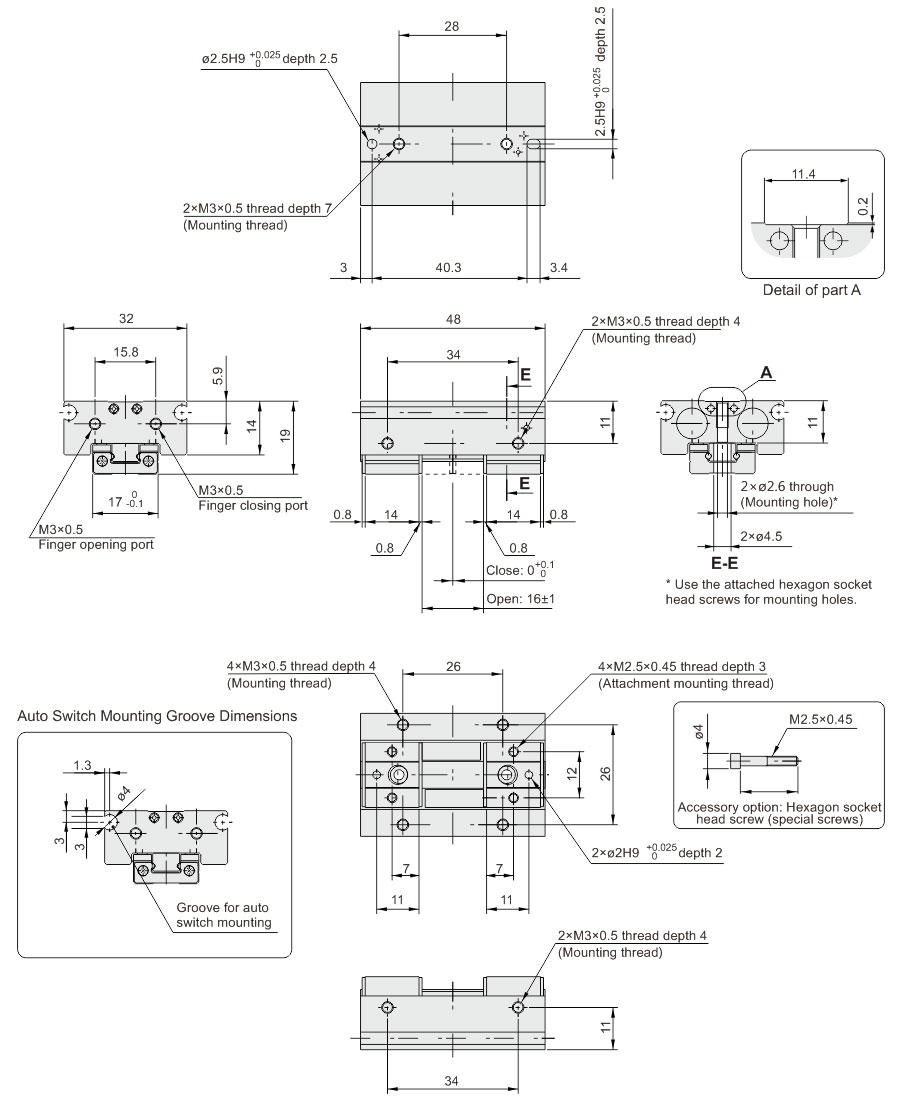
MHF2-8D2
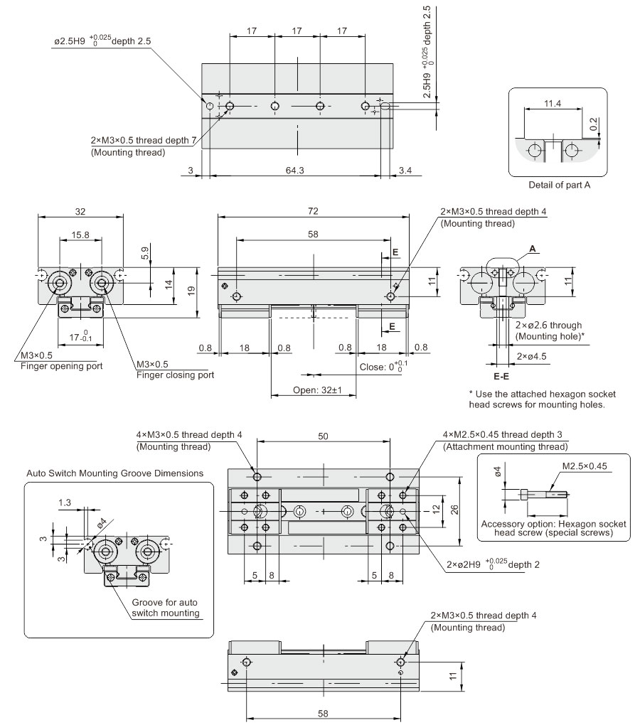
MHF2-12D
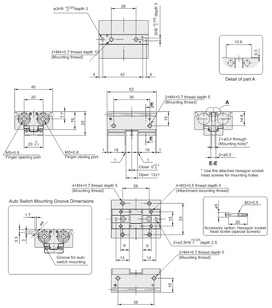
MHF2-12D1
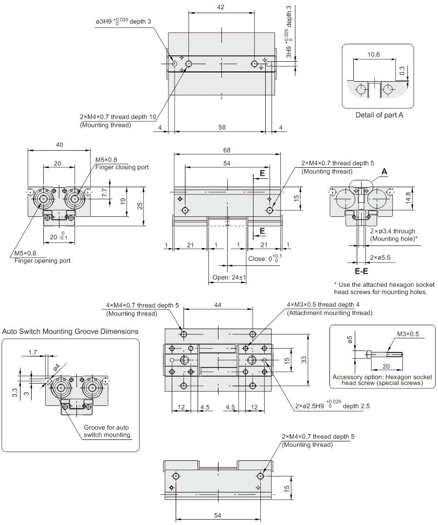
MHF2-12D2
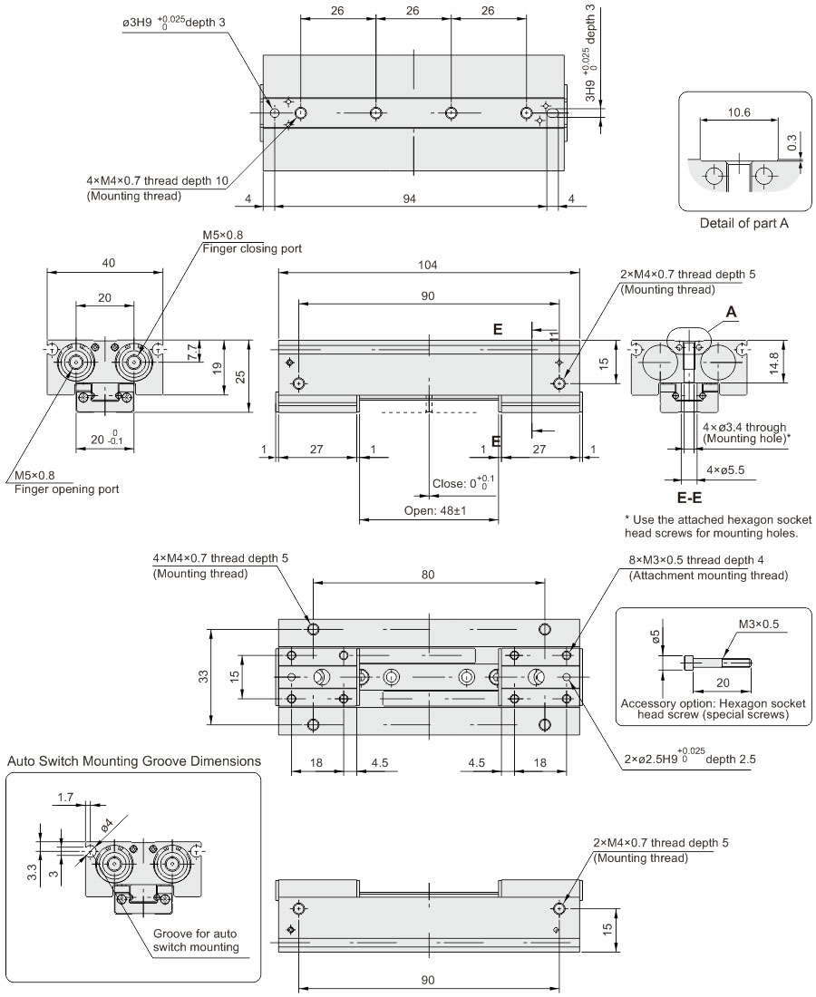
MHF2-16D
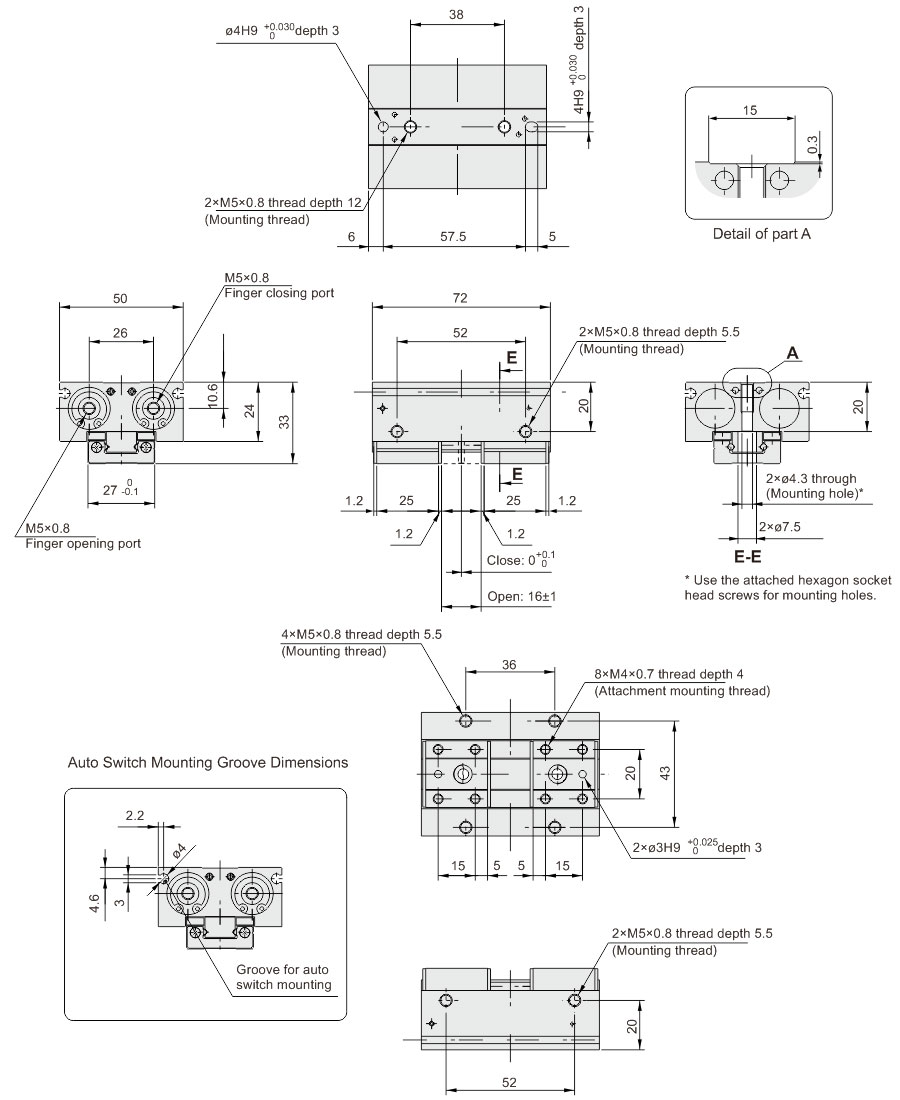
MHF2-16D1
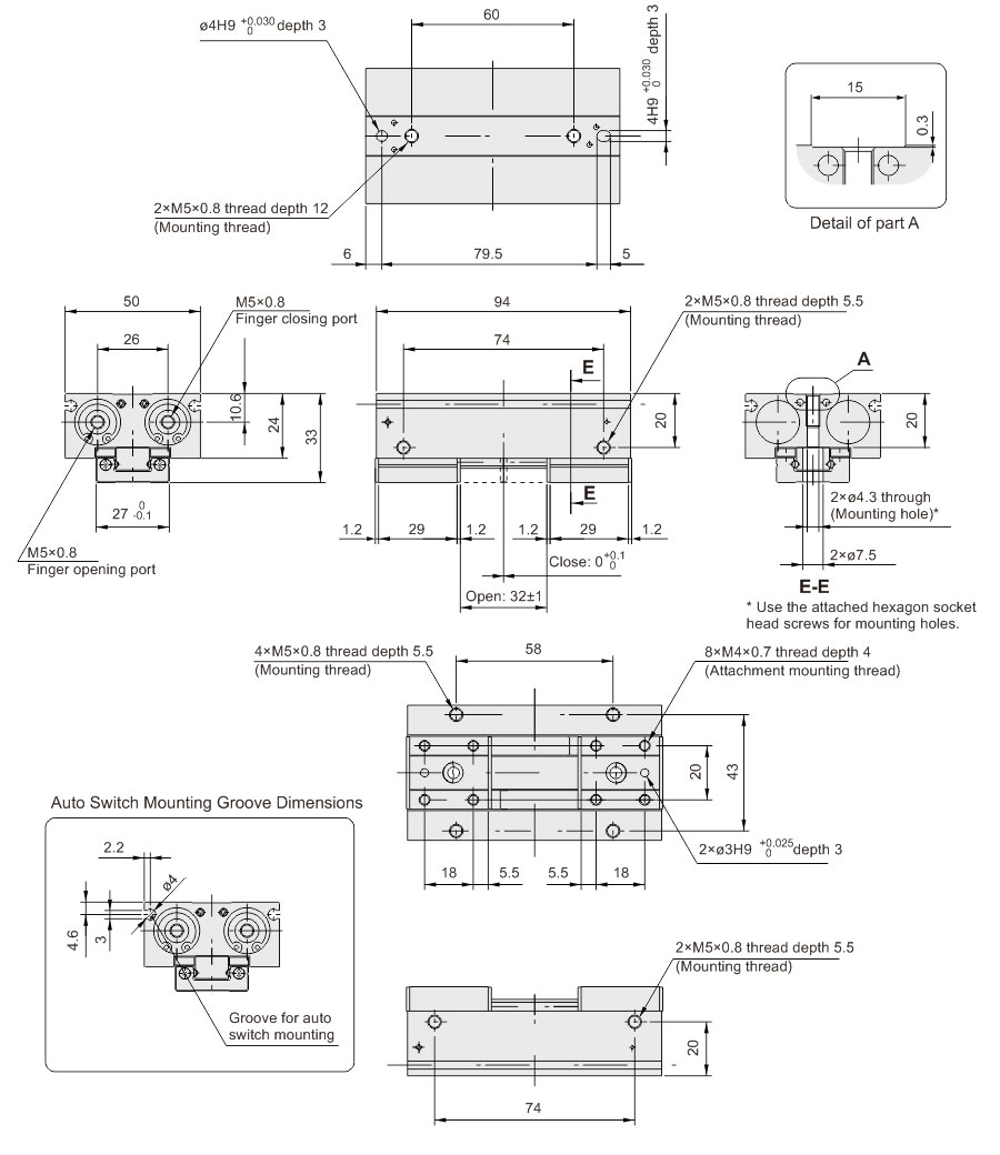
MHF2-16D2
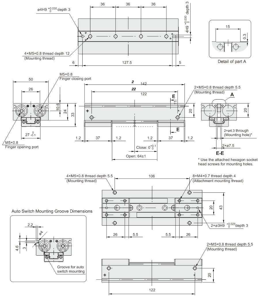
MHF2-20D
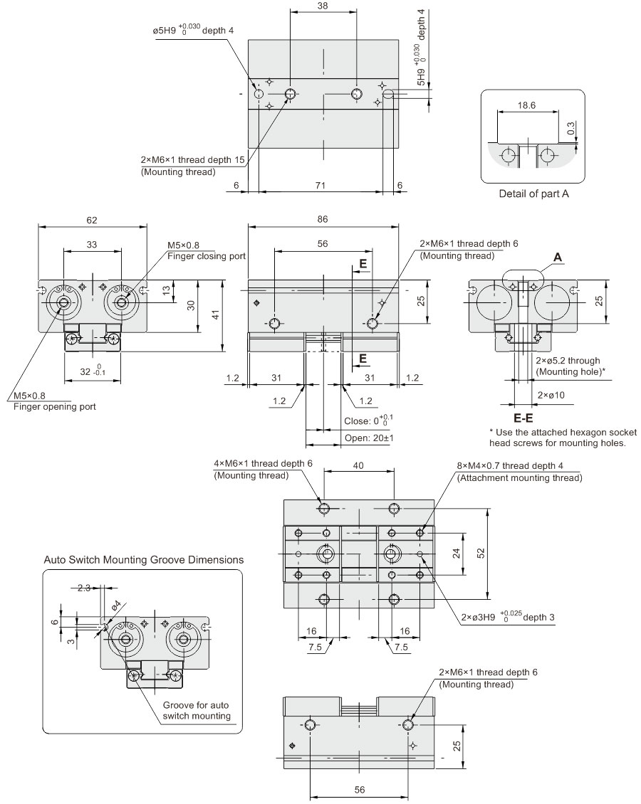
MHF2-20D1
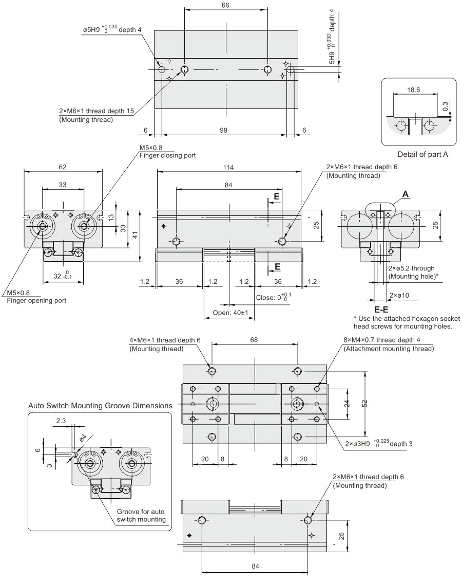
MHF2-20D2
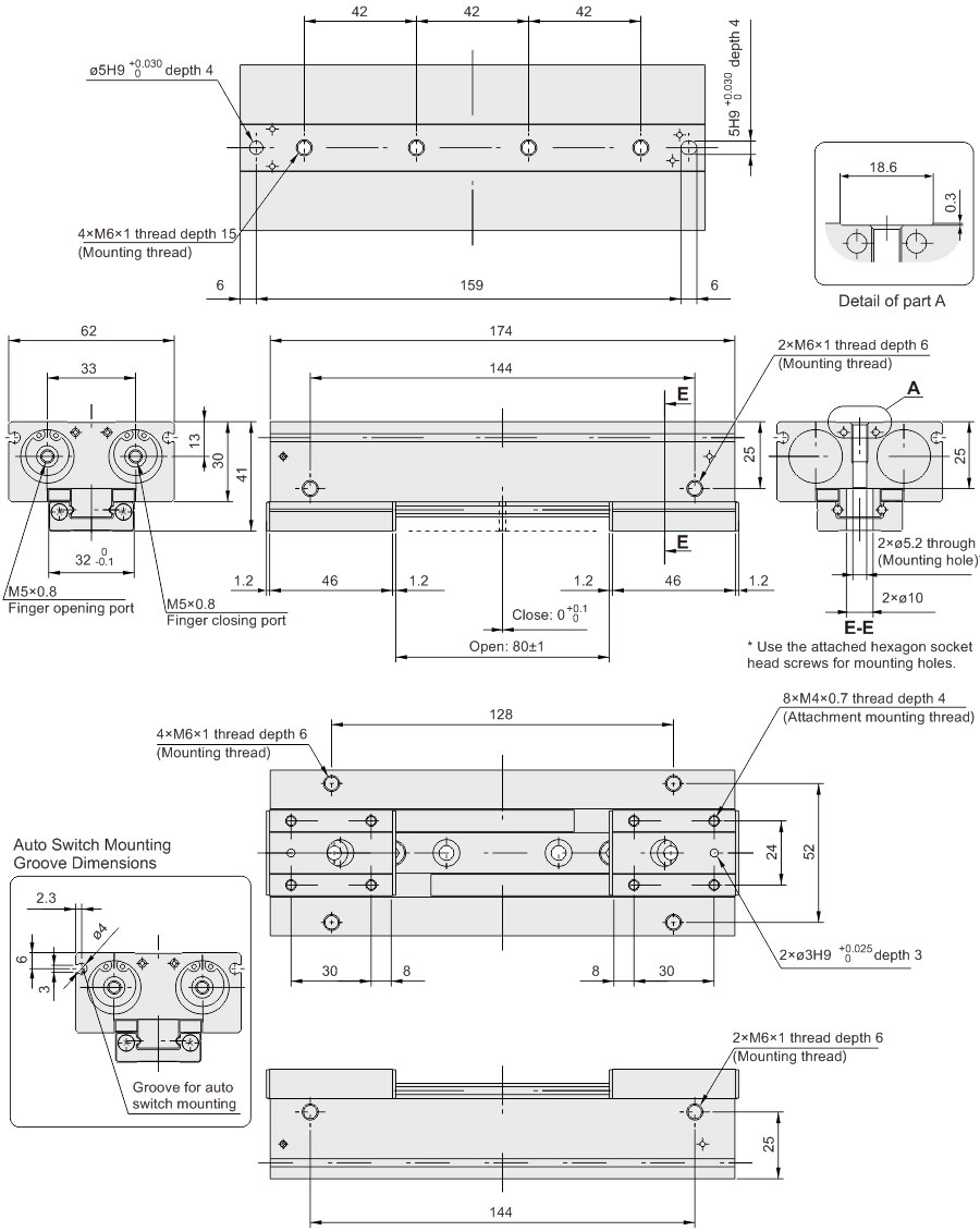
Body Option: Side Piping Type

Body Option Dimension (mm)
| Model |
A |
B |
C |
D |
| MHF2-8DR |
5.5 |
25 |
11 |
M3×0.5 |
| MHF2-8D1R |
37 |

Body Option Dimension (mm)
| Model |
A |
B |
C |
D |
| MHF2-8D2R |
5.5 |
61 |
11 |
M3×0.5 |
| MHF2-12DR |
7 |
38 |
14.8 |
M5×0.8 |
| MHF2-12D1R |
54 |
| MHF2-12D2R |
90 |
| MHF2-16DR |
9 |
54 |
19 |
M5×0.8 |
| MHF2-16D1R |
76 |
| MHF2-16D2R |
124 |
| MHF2-20DR |
10 |
66 |
23 |
M5×0.8 |
| MHF2-20D1R |
94 |
| MHF2-20D2R |
154 |
* For dimensions not given above, please contact us.
Auto Switch Installation Examples and Mounting Positions
Various auto switch applications are possible through different combinations of auto switch quantities and detecting positions.
1) Detection when Gripping Exterior of Workpiece
| Detection example |
1. Confirmation of fingers in
reset position |
2. Confirmation of workpiece
held |
3. Confirmation of workpiece released |
| Position to be detected |
 |
 |
 |
| Operation of auto switch |
Auto switch turned on when fingers return. (Light ON) |
Auto switch turned on when gripping a workpiece. (Light ON) |
When a workpiece is not held (Abnormal operation): Auto switch to turn ON. (Light ON) |
| Detection Combinations |
One auto switch
*One position, any of 1, 2 and 3 can be detected. |
● |
● |
● |
Two auto switches
*Two positions, any of 1, 2 and 3 can be detected. |
Pattern |
A |
● |
● |
- |
| B |
- |
● |
● |
| C |
● |
- |
● |
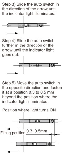
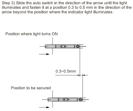
How to determine auto switch installation position
At no pressure or low pressure, connect the auto switch to a power supply, and follow the directions.
|
 |
 |
 |
 |
 |
 |
Note 1) It is recommended that gripping of a workpiece be performed close to the center of the finger stroke.
Note 2) When holding a workpiece close at the end of open/close stroke of fingers, detecting performance of the combinations listed in the above table may be limited, depending on the hysteresis of an auto switch, etc.
2) Detection when Gripping Interior of Workpiece
| Detection example |
1. Confirmation of fingers in
reset position |
2. Confirmation of workpiece
held |
3. Confirmation of workpiece released |
| Position to be detected |
 |
 |
 |
| Operation of auto switch |
Auto switch turned on when fingers return. (Light ON) |
Auto switch turned on when gripping a workpiece. (Light ON) |
When a workpiece is not held (Abnormal operation): Auto switch to turn ON. (Light ON) |
| Detection Combinations |
One auto switch
*One position, any of 1, 2 and 3 can be detected. |
● |
● |
● |
Two auto switches
*Two positions, any of 1, 2 and 3 can be detected. |
Pattern |
A |
● |
● |
- |
| B |
- |
● |
● |
| C |
● |
- |
● |
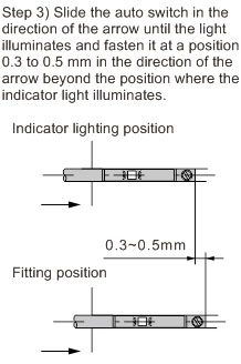
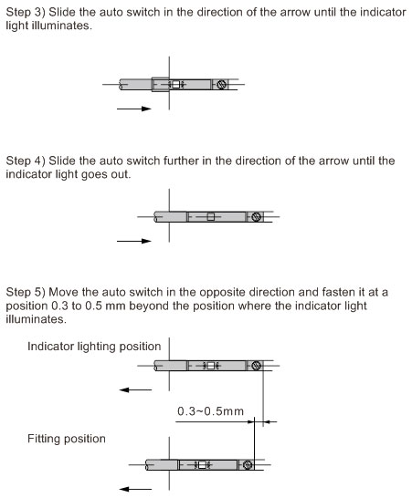
How to determine auto switch installation position
At no pressure or low pressure, connect the auto switch to a power supply, and follow the directions.
|
 |
 |
 |
 |
 |
 |
Note 1) It is recommended that gripping of a workpiece be performed close to the center of the finger stroke.
Note 2) When holding a workpiece close at the end of open/close stroke of fingers, detecting performance of the combinations listed in the above table may be limited, depending on the hysteresis of an auto switch, etc.
Auto Switch Hysteresis
Auto switches have hysteresis similar to micro switches. Use the table below as a guide when adjusting aut switch positions.
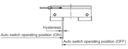
Hysteresis
|
D-M9□(V)
D-M9□W(V)
D-M9□A(V) |
| MHF2-8D□ |
0.2 |
| MHF2-12D□ |
0.3 |
| MHF2-16D□ |
0.2 |
| MHF2-20D□ |
0.5 |
Auto Switch Mounting
Insert the auto switch into the auto switch mounting groove in the air chuck in th direction shown below, and after setting the mounting position, tighten the attached switch mounting screw with a flat head watchmaker's screwdriver.
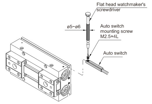
Note) Use a watchmaker's screwdriver with a grip diameter of 5 to 6 mm to tighten the auto switch mounting screw. The tightening torque should be about 0.05 to 0.15 N·m.
Protrusion of Auto Switch from Edge of Body
• The amount of auto switch protrusion from the body end surface is shown in the table below.
• Use this as a standard when mounting, etc.
Protrusion of Auto switch
| Lead wire type |
In-line entry |
Perpendicular entry |
| Illustration |
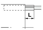 |
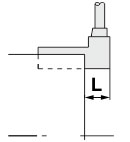 |
| Model |
Auto switch /
Finger position |
D-M9□
D-M9□W |
D-M9□A |
D-M9□V
D-M9□WV |
D-M9AV |
| MHF2-8D |
Open |
6.5 |
8.5 |
4.5 |
6.5 |
| Close |
6.5 |
8.5 |
4.5 |
6.5 |
| MHF2-8D1 |
Open |
6.5 |
8.5 |
4.5 |
6.5 |
| Close |
6.5 |
8.5 |
4.5 |
6.5 |
| MHF2-8D2 |
Open |
0.5 |
2.5 |
―― |
―― |
| Close |
0.5 |
2.5 |
―― |
―― |
| MHF2-12D |
Open |
3 |
5 |
1 |
3 |
| Close |
3 |
5 |
1 |
3 |
| MHF2-12D1 |
Open |
1 |
3 |
―― |
―― |
| Close |
1 |
3 |
―― |
―― |
| MHF2-12D2 |
Open |
―― |
―― |
―― |
―― |
| Close |
―― |
―― |
―― |
―― |
| MHF2-16D |
Open |
―― |
―― |
―― |
―― |
| Close |
―― |
―― |
―― |
―― |
| MHF2-16D1 |
Open |
―― |
―― |
―― |
―― |
| Close |
―― |
―― |
―― |
―― |
| MHF2-16D2 |
Open |
―― |
―― |
―― |
―― |
| Close |
―― |
―― |
―― |
―― |
| MHF2-20D |
Open |
―― |
―― |
―― |
―― |
| Close |
―― |
―― |
―― |
―― |
| MHF2-20D1 |
Open |
―― |
―― |
―― |
―― |
| Close |
―― |
―― |
―― |
―― |
| MHF2-20D2 |
Open |
―― |
―― |
―― |
―― |
| Close |
―― |
―― |
―― |
―― |
Note) There is no protrusion for sections of the table with no values entered.
Caution
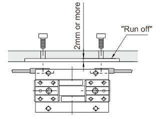
When using an auto switch on the mounting plate side, the switch will protrude from the end face as shown in the right figure.
Please provide a run off space of 2 mm or more on the mounting plate.
